- 您现在的位置:买卖IC网 > Sheet目录234 > MCC95-18IO1B (IXYS)MOD THYRISTOR DUAL 1800V TO240AA
MCC 95
MCD 95
3000
10 5
V R = 0 V
250
I t
[A s]
2500
2000
I TSM
1500
[A]
1000
500
50 Hz
80% V RRM
T VJ = 45°C
T VJ = 125°C
2
2
T VJ = 45°C
T VJ = 125°C
200
I TAVM
150
[A]
100
50
DC
180° sin
120°
60°
30°
t [ms]
0
0.001 0.01 0.1 1
t [s]
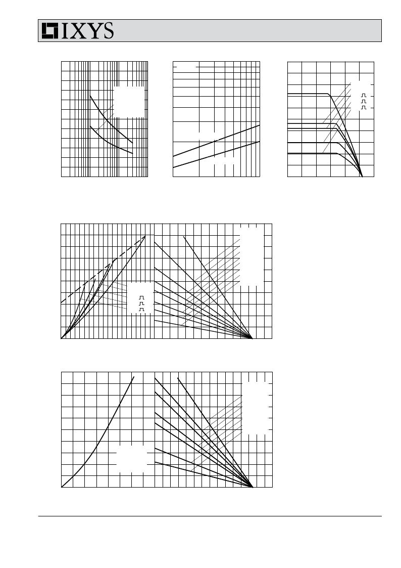
Fig. 3 Surge overload current I TSM ,
I FSM : Crest value, t: duration
10 4
1
Fig. 4 I 2 t versus time (1-10 ms)
10
0
0 25 50 75 100 125 150
T C [°C]
Fig. 4a Maximum forward current
at case temperature
250
R thKA K/W
0.4
200
0.6
0.8
P tot
150
[W]
100
50
DC
180° sin
120°
60°
30°
1
1.2
1.5
2
3
Fig. 5 Power dissipation versus
on-state current & ambient
temperature
0
0
50
100
150
0
50
100
150
(per thyristor or diode)
I TAVM , I FAVM [A]
T a [°C]
1000
R thKA K/W
800
P tot
600
[W]
0.03
0.06
0.08
0.12
0.15
0.3
0.5
400
Circuit
B6
200
3x MCC95 or
3x MCD95
Fig. 6 Three phase rectifier bridge:
Power dissipation vs. direct
output current and ambient
0
0
100
200
300
0
50
100
150
temperature
I dAVM [A]
T a [°C]
IXYS reserves the right to change limits, test conditions and dimensions.
? 2010 IXYS All rights reserved
20101116a
4-5
发布紧急采购,3分钟左右您将得到回复。
相关PDF资料
MCD310-22IO1
MOD THYRISTOR/DIODE 2200V Y2-DCB
MD-1962
BOX FUTURA SMALL METAL 8"X16"X9"
MD2721
SWITCH PLUNGER ASSMBLY
MD3211Q5
SWITCH WHEEL PLUNGER ASSMBLY
MDA3711Q
SWITCH WHEEL PLUNGER ASSMBLY
MDP1603110RGE04
RES ARRAY 110 OHM 8 RES 16-DIP
MEC1-160-02-F-D-EM2
CONN EDGE CARD DL 120POS SMD
MEC1-170-02-S-D-A-K
CONN EDGE CARD DL 140POS SMD
相关代理商/技术参数
MCC95-18io8B
功能描述:分立半导体模块 95 Amps 1800V RoHS:否 制造商:Infineon Technologies 产品:Thyristor Power Modules 类型:Phase Controls 安装风格:Screw 封装 / 箱体:DT61 封装:
MCC95M10
制造商:Thomas & Betts 功能描述:METRIC CONNECTOR 95MMSQ M10 STUD
MCC95M12
制造商:Thomas & Betts 功能描述:METRIC CONNECTOR 95MMSQ M12 STUD
MCC95M14
制造商:Thomas & Betts 功能描述:METRIC CU CONNECTOR 95SQMM M14 STUD
MCC95M16
制造商:Thomas & Betts 功能描述:METRIC CONNECTOR 95MMSQ M16 STUD
MCC95M20
制造商:Thomas & Betts 功能描述:METRIC CU CONNECTOR 95SQMM M20 STUD
MCC95M6
制造商:Thomas & Betts 功能描述:METRIC CONNECTOR 95MMSQ M6 STUD
MCC95M8
制造商:Thomas & Betts 功能描述:METRIC CONNECTOR 95MMSQ M8 STUD
